Microfreak/UG/05 Connections
05 Making Connections
05.1 Control Signals
- The Matrix connects control signals from the MicroFreak's modules. These signals move more slowly than audio and are suited to controlling sound.
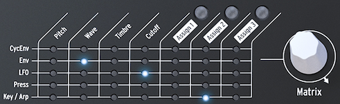
- The MicroFreak Matrix
- Control signals usually move between 0 and 100 Hz. They can modulate the Digital Oscillator, Analog Filter, and other destinations. The Matrix encoder sets their amount from -100% to +100%.
- The MicroFreak's modules generate control signals in different ways.
- The LFO makes slow, regular waves. Routed to oscillator pitch, it makes the pitch rise and fall; it can reach 100 Hz.
- An envelope rises once, then gradually fades. Routed to oscillator pitch, it creates a quick rise followed by a descent. The Cycling Envelope can repeat, acting as a second LFO with more complex modulation waves.
- A gate rises at Note On and falls at Note Off. The keyboard sends gates that start the MicroFreak's envelope.
- Three kinds of control signals are used: triggers, gates, and waves.
- Triggers are very short spikes that start an envelope, LFO, or sequencer. Clocks generate triggers.
- Gates last longer and keep something active, such as an envelope's hold stage. A keyboard sends a gate while a key is held.
- Waves can last any length and usually cycle from high to low and back. The MicroFreak's LFO and two envelopes create slow waves.
- Control signals give a MicroFreak performer room to develop a personal style, as color and line do for a painter.
- Note for advanced users: Analog synthesizers and modular systems use control voltages for modulation. Mostly digital synthesizers such as the MicroFreak use digital signals that mimic those voltages; this manual calls them control signals.
05.2 The Matrix and its encoder
- The Matrix links control signals from sources to destinations.
- A classic synthesizer sends an oscillator through a filter and then an amplifier. The Matrix lets you override those fixed connections and route triggers, gates, LFO waves, and envelopes to the Digital Oscillator and Filter.
- The Matrix is the main switchboard for creating, changing, and mixing modulation connections. It has a switchboard and an encoder for selecting connections and setting their modulation amount.
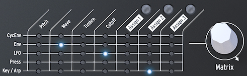
- The Matrix and its encoder
- Turn the encoder to choose a source–destination point, then press it to create or edit the connection. It scrolls forward or backward and wraps at the end of the Matrix.
- The Matrix shows each connection's state:
- LED off: no connection is active, or its amount is zero.
- LED on: a connection is active.
- LED blinking: the connection is selected and its modulation amount is being edited.
- The display shows the selected connection and its current modulation amount. Press the encoder to edit the amount; the display inverts and only that connection's LED stays lit. Changes take effect immediately.
- Multiple sources can control the same destination. For example, Key/Arp and the LFO can both affect oscillator pitch, and their modulation amounts are added together. With a rectangular LFO wave, this can transpose a sequence up and down at the LFO rate.
- Setting a connection's amount to zero turns it off. To clear a Matrix point and reset its amount, hold the encoder for at least 0.5 seconds.
- To create and edit a connection:
- Turn the encoder to select a point and press it.
- Turn the encoder to set a positive or negative modulation amount.
- To disable a connection and reset its amount:
- Select the connection with the encoder.
- Hold the encoder for at least 0.5 seconds, or set its amount to zero.
05.2.1 Sources and Destinations
- The Matrix has 35 patch points: five sources on the left and seven destinations across the top.
- Its sources are:
- CycEnv: output of the Cycling Envelope Generator.
- ENV: output of the Envelope Generator.
- LFO: output of the Low-Frequency Oscillator.
- PRESSURE: pressure or velocity output, depending on the Utility setting.
- KEY / ARP: combined output of the keyboard, arpeggiator, and sequencer.
- The first four destinations are Pitch, Wave, Timbre, and Cutoff.
- Pitch, Wave, and Timbre modify the Digital Oscillator's sound.
- Cutoff changes the Filter's cutoff frequency. The Digital Oscillator passes through the Analog Filter, which can remove or emphasize frequencies. See Microfreak/UG/07 Filter.
05.2.2 Assigning destinations
- Assign1, Assign2, and Assign3 are user-defined destinations. They can turn nearly any MicroFreak knob into a modulation destination.
- Master Volume and the Preset Encoder cannot be assigned. Shift-plus-knob parameters, control buttons, and icon buttons such as Spice and Dice cannot be assigned either.
- To assign a destination to one source:
- Select its Assign point in the Matrix and press the encoder to enter edit mode.
- Hold the corresponding Assign button and turn the knob to use as a destination. The display confirms the parameter.
- Turn the encoder to set the modulation amount, then press it to leave edit mode.
- To assign one destination to every source in a column, hold an Assign button and move the desired knob. Then set the amount for each source in that column.
- Possible modulation destinations include:
- Glide: Glide amount.
- Oscillator Type: oscillator model.
- Sample: sample slot index.
- Oscillator Wave, Timbre, and Shape: the corresponding parameter of the selected oscillator.
- Filter Cutoff and Resonance: cutoff frequency and filter bandwidth.
- Envelope Attack, Decay, Sustain, and Filter Amount: the Standard Envelope stages and its amount sent to the amplifier.
- LFO Rate: LFO speed.
- Arp&Seq Rate: arpeggiator and sequencer rate.
- Cycling Envelope Rise, Fall, and Hold: the Cycling Envelope's stages.
- Cycling Envelope Amount: amount sent from CycEnv to the Matrix.
- Matrix Modulation Amount: modulation amount of a Matrix point.
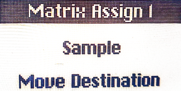
- Starting with MicroFreak firmware 5.0.0, Sample can be assigned by opening the Sample select menu, pressing one of the three Assign buttons, and turning the Type knob.
- Sample assigned as a Matrix destination
- A Matrix connection's modulation amount can itself be modulated. To vary vibrato depth with the Cycling Envelope:
- Route the LFO to oscillator Pitch.
- Select CycEnv→Assign1 in the Matrix and hold Assign1.
- Select the LFO→Pitch point and press the encoder to make it the modulation-amount destination.
- Return to CycEnv→Assign1 and set its amount. The Cycling Envelope now changes the vibrato depth.
- In Paraphonic mode, all voices are assigned simultaneously as a destination.
- To clear all Matrix routings, hold Shift and press the Matrix encoder.
- The Matrix routes sources to destinations and mixes multiple sources at one destination. The encoder sets modulation strength in either a positive or negative direction.
05.3 Freaky ideas
- Modulation often works best below full strength; the right amount can add subtlety and expression to a patch. The Matrix offers many ways to find unusual sounds.
- Change pitch scope: The keyboard and a sequence already modulate oscillator pitch at one volt per octave. Routing Key/Arp to Pitch can widen sequence steps to two or four semitones; negative modulation can shrink them to microtonal intervals.
- Sum modulation signals: Combine the Standard and Cycling Envelope outputs at one destination to create a complex control signal for the filter or arpeggiator rate.
- Mix the Cycling Envelope and LFO: Combining them at Filter Cutoff creates a composite modulation that can behave in surprising ways.
- Modulate the Digital Oscillator: Let an unsynced LFO and Cycling Envelope control Wave, Timbre, and Shape at different speeds to create evolving timbral patterns.
- Create regular automatic transpositions: Use the LFO's Random wave to modulate Pitch, or a slow square wave for more regular transpositions. The square-wave approach also works with a sequence.
- Modulate modulation: Sequencer modulation tracks can change the strength of a Matrix connection. Hold an Assign button, select a Matrix point, then release the button to set that point as a destination. The LFO and Cycling Envelope can also modulate connection strength.
- Modulate Cycling Envelope timing: Use the LFO to control its own rate, or use the Cycling Envelope to control its own rise time, fall time, or amount.
- Create circular routings: Let the LFO control the Cycling Envelope's rise or fall time, then let the Cycling Envelope control its own level. The EMS Synthi became known for these distinctive, difficult-to-repeat routings.